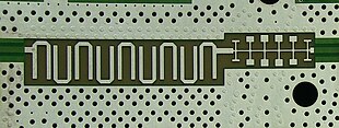
Planar transmission lines are transmission lines with conductors, or in some cases dielectric (insulating) strips, that are flat, ribbon-shaped lines. They are used to interconnect components on printed circuits and integrated circuits working at microwave frequencies because the planar type fits in well with the manufacturing methods for these components. Transmission lines are more than simply interconnections. With simple interconnections, the propagation of the electromagnetic wave along the wire is fast enough to be considered instantaneous, and the voltages at each end of the wire can be considered identical. If the wire is longer than a large fraction of a wavelength (one tenth is often used as a rule of thumb), these assumptions are no longer true and transmission line theory must be used instead. With transmission lines, the geometry of the line is precisely controlled (in most cases, the cross-section is kept constant along the length) so that its electrical behaviour is highly predictable. At lower frequencies, these considerations are only necessary for the cables connecting different pieces of equipment, but at microwave frequencies the distance at which transmission line theory becomes necessary is measured in millimetres. Hence, transmission lines are needed within circuits.
The earliest type of planar transmission line was conceived during World War II by Robert M. Barrett. It is known as stripline, and is one of the four main types in modern use, along with microstrip, suspended stripline, and coplanar waveguide. All four of these types consist of a pair of conductors (although in three of them, one of these conductors is the ground plane). Consequently, they have a dominant mode of transmission (the mode is the field pattern of the electromagnetic wave) that is identical, or near-identical, to the mode found in a pair of wires. Other planar types of transmission line, such as slotline, finline, and imageline, transmit along a strip of dielectric, and substrate-integrated waveguide forms a dielectric waveguide within the substrate with rows of posts. These types cannot support the same mode as a pair of wires, and consequently they have different transmission properties. Many of these types have a narrower bandwidth and in general produce more signal distortion than pairs of conductors. Their advantages depend on the exact types being compared, but can include low loss and a better range of characteristic impedance. (Full article...)