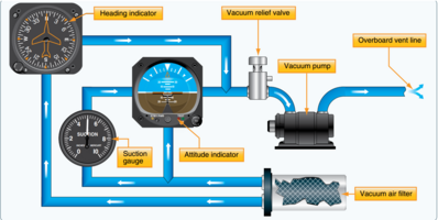
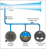
The heading indicator (HI), also known as a directional gyro[1] (DG) or direction indicator (DI),[2][3][4][5] is a flight instrument used in an aircraft to inform the pilot of the aircraft's heading.


Use
editThe primary means of establishing the heading in most small aircraft is the magnetic compass, which, however, suffers from several types of errors, including that created by the "dip" or downward slope of the Earth's magnetic field. Dip error causes the magnetic compass to read incorrectly whenever the aircraft is in a bank, or during acceleration or deceleration, making it difficult to use in any flight condition other than unaccelerated, perfectly straight and level. To remedy this, the pilot will typically maneuver the airplane with reference to the heading indicator, as the gyroscopic heading indicator is unaffected by dip and acceleration errors. The pilot will periodically reset the heading indicator to the heading shown on the magnetic compass.[4][6][7][8]
Operation
editThe heading indicator works using a gyroscope, tied by an erection mechanism to the aircraft yawing plane, i. e. the plane defined by the longitudinal and the horizontal axis of the aircraft. As such, any configuration of the aircraft yawing plane that does not match the local Earth horizontal results in an indication error. The heading indicator is arranged such that the gyro axis is used to drive the display, which consists of a circular compass card calibrated in degrees. The gyroscope is spun either electrically, or using filtered air flow from a suction pump (sometimes a pressure pump in high altitude aircraft) driven from the aircraft's engine. Because the Earth rotates (ω, 15° per hour, apparent drift), and because of small accumulated errors caused by imperfect balancing of the gyro, the heading indicator will drift over time (real drift), and must be reset using a magnetic compass periodically.[4][a] The apparent drift is predicted by ω sin Latitude and will thus be greatest over the poles. To counter for the effect of Earth rate drift a latitude nut can be set (on the ground only) which induces a (hopefully equal and opposite) real wander in the gyroscope. Otherwise it would be necessary to manually realign the direction indicator once each ten to fifteen minutes during routine in-flight checks. Failure to do this is a common source of navigation errors among new pilots. Another sort of apparent drift exists in the form of transport wander, caused by the aircraft movement and the convergence of the meridian lines towards the poles. It equals the course change along a great circle (orthodrome) flight path. [9]
Variations
editSome more expensive heading indicators are "slaved" to a magnetic sensor, called a flux gate. The flux gate continuously senses the Earth's magnetic field, and a servo mechanism constantly corrects the heading indicator.[4] These "slaved gyros" reduce pilot workload by eliminating the need for manual realignment every ten to fifteen minutes.
The prediction of drift in degrees per hour, is as follows:
| Source | Drift rate (°/hr) | Sign, by hemisphere | |
|---|---|---|---|
| Northern | Southern | ||
| Earth rate | 15 sin(operating latitude) | − (causing an under-read) | + (causing an over-read) |
| Latitude nut | 15 sin(latitude of setting) | + | − |
| Transport wander, East | East ground speed component (or, sin(track angle) × ground speed, or, change in longitude/flight time in hours) × 1⁄60tan(operating latitude) | − | + |
| Transport wander, West | West ground speed component (or sin(track angle) × ground speed or change in longitude/flight time in hours) × 1⁄60tan(operating latitude) | + | − |
| Real/random wander | As given in the aircraft operating manual | As given | As given |
Although it is possible to predict the drift, there will be minor variations from this basic model, accounted for by gimbal error (operating the aircraft away from the local horizontal), among others. A common source of error here is the improper setting of the latitude nut (to the opposite hemisphere for example). The table however allows one to gauge whether an indicator is behaving as expected, and as such, is compared with the realignment corrections made with reference to the magnetic compass. Transport wander is an undesirable consequence of apparent drift.
See also
edit- Acronyms and abbreviations in avionics
- Earth Inductor Compass
- Gyrocompass, a compass depending on gyroscopic precession effect instead of a basic gyroscopic effect
- Horizontal situation indicator
- Inertial navigation system, a far more complex system of gyroscopes that also employ accelerometers
References
editFootnotes
edit- ^ As a heading indicator ages and its ball bearings become worn and noisy, thus increasing friction, the tendency to drift will increase.
Notes
edit- ^ Grumman F11F Tiger Pilot's Flight Operating Instructions. United States Navy. 1 September 2008. p. 51. ISBN 978-1-935327-46-2. Retrieved 17 February 2022.
- ^ Rotorcraft Flying Handbook FAA-H-8083-21A. Federal Aviation Authority. 2012. p. 12-3.
- ^ Kjellstrom, Bjorn; Elgin, Carina Kjellstrom (9 December 2009). Be Expert with Map and Compass. John Wiley & Sons. p. 73. ISBN 978-0-470-40765-3. Retrieved 17 February 2022.
- ^ a b c d Bowditch, Nathaniel. American Practical Navigator, Paradise Cay Publications, 2002, pp.93-94, ISBN 978-0-939837-54-0.
- ^ "Inside the Cockpit of Amelia Earhart's Vega". airandspace.si.edu. 25 February 2019. Retrieved 17 February 2022.
- ^ NASA NASA Callback: Heading for Trouble, NASA Callback Safety Bulletin website, December 2005, No. 305. Retrieved August 29, 2010.
- ^ Instrument Flying Handbook, FAA-H-8083-15B (PDF). U.S. Dept. of Transportation, FAA. 2012. p. 5-19,5-20.
- ^ Pilot's Handbook of Aeronautical Knowledge, FAA-H-8083-25B (PDF). U.S. Dept. of Transportation, FAA. 2016. p. 8-19,8-20.
- ^ Peck, James L. H. (March 1944). "How Aircraft Instruments Work". Popular Science. Vol. 144, no. 3. New York, New York: Popular Science Publishing Company. p. 119. Retrieved 31 January 2023.

